

Contents

Software Development Methodologies
Before getting deeper into each methodology, I want to point out the difference between application lifecycle management (ALM) and software development lifecycles (SDLC) or methodologies.
ALM is a broader perspective than SDLC, since ALM involves the whole product lifecycle management from conception to retirement (governance, development, and maintenance).
SDLC is specific to the phases of software development such as requirements, design, coding, testing, configuration, project management, and change management.
There are a broad number of SDLC models like Waterfall, V Model, Spiral, Rational Unified Proces (RUP), Agile, Lean, etc., here we are only focusing on three, Waterfall, Agile and Lean.

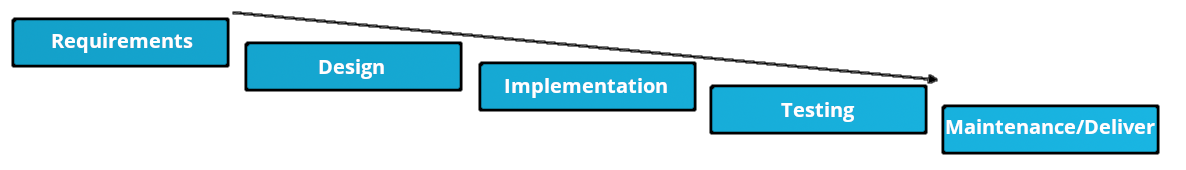
Waterfall
This model is one of the oldest, and is a breakdown of activities into linear sequential phases (order is fundamental), where each phase depends on the deliverables of the previous one.
In principle, a new phase should not begin until the current phase ends, and past phases should not be returned to.
These are some of the rules to determine the closure of a phase: (In practice they are not always followed)
- Completion of the documentation for that phase
- Exit criteria for current phase completed.
- Entrance criteria for the new phase completed.
Advantages
- Simple to understand, implement and manage
- Proven and well-known
- Simple resource allocation
- Good fit for small projects
Disadvantages
- Clear and complete requirements from start, commonly not achieved
- Delayed feedback, usually stakeholders provide feedback after Testing Phase
- Problems detected late. Impact of these could be critical
- Difficult to estimate
- No parallel processes
- Inefficient resource use
Agile & Lean
Sometimes these two are mistakenly used as synonyms. Lean and Agile software development in essence would have almost the same goal, but different origins that differentiate their frameworks.
- Agile refers to a set of values and principles set out in the Agile Manifesto, a brief document built on 4 values and 12 principles for agile software development, this document is not prescriptive and does not outline any specific processes, procedures, or best practices for agile, there is where the frameworks like Scrum come in place.
- Lean has its origins in manufacturing where described a model based on the Toyota Production System (TPS). TPS was focused on the "elimination of waste" and the resulting methods were defined in "The Machine that Changed the World" (Womack, Jones and Roos 1990) and further detailed by James Womack and Daniel Jones in "Lean Thinking" (1996).
The principles from manufacturing were eventually extrapolated to software development. Some books on applying those principles are Dr. Robert Charette "Lean Software Development" and "12 Principles of Lean Software Development".
Tom and Mary Poppendieck also published "Lean Software Development: An Agile Toolkit" with seven principles of Lean Development.
Similarities
- Agile & Lean try to optimize the time of delivery of a product, instead of large productions. Lean does it in the least possible (efficient) number of lots and Agile providing many frequent versions of a product.
- Both look for continuous improvements, in Lean methodology this is called "Kaizen", and both have focus on cooperation between teammates.
- Also, the main goal for both methodologies is to create valuable results for the client.
Differences
- The main difference is that the Agile methodology concerns the optimization of a development process, while the Lean method comes from the optimization of a production process and now is extrapolated to software development.
- Agile welcomes change and allows the client to constantly adapt his needs, while in a Lean production, variation and rework are negative and expensive. Remember that Lean provides the manufacture of a product without waste.
- In a development process, prototypes are foreseen, which are first tested and evaluated in order to then develop the final product. In a production process, the work ultimately translates into a final product that is produced as efficiently as possible.
Advantages
- Fast deliveries
- Foster teamwork and skill sharing
- Transforms the linear sequence into a more continuous improved process
- Strong customer relationships
- Agile requires less planning
- Lean focus on less infrastructure / less waste
Disadvantages
- Requires customer interaction (It could also be an advantage). Some customers are not used to provide regular feedback
- Agile is focused on software development, not documentation, so this increases dependency on people
- Some Agile frameworks require involved team leaders (scrum master).
- Lean production have little room for error (equipment or labor failure), in exchange for those optimized efficiency advantages.
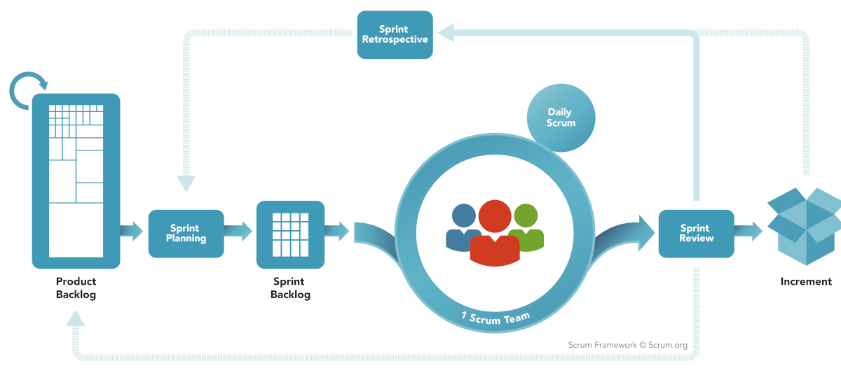
Scrum
Scrum is a prescriptive, incremental and iterative general agile framework, in which one of the most relevant phases in that framework are the sprints. Each Sprint may be considered a mini-project with no more than a one-month horizon, and like projects, each Sprint has a goal, a design, a flexible plan, the work, and the resultant product increment.
Scrum teams are comprised of 6-9 people and one of them is designated as a “Scrum Master”, additionally to the Master, there are some other roles in the team, “Product Owner”, “Developer” and “Tester”.
Meetings are held daily, no longer than 15 min, and there should be only 3 questions asked on these:
- What items have been completed since the last meeting?
- What issues have been discovered?
- What are the new assignments for the next meeting?
Since Scrum is an extensive topic on its own, I’ll just scratch the surface this time. To keep an idea of this framework phases, next is the general diagram of the Scrum framework.
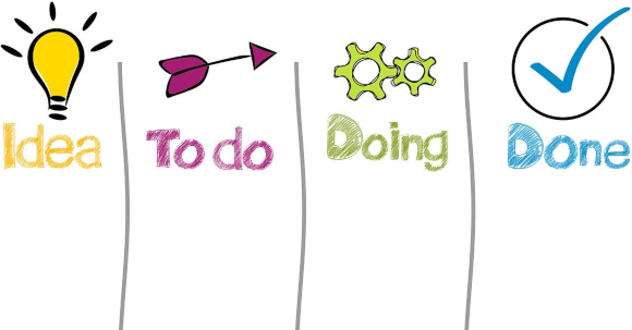
Kanban
Kanban is a visual signaling mechanisms to control work in progress for products, it focuses on visualization, flow, and limiting work in progress.
Kanban is similar to Scrum, but it doesn’t have sprint intervals, there is a backlog of items and vertical columns for each status that a work item can have. This items move from one status to another, and the work in progress (WIP) is limited to a maximum number of items based on the team capacity.
This method is more lightweight or informal since it doesn’t have sprint planning, demos, retrospectives, etc. This implies that there is no need for a team leader, the team becomes task-oriented, but the lack of team leaders require discipline from team members and they must police each other.
The goal is to reduce lead time, but this could encourage recklessness, so testing for quality is an important part of the process

Coding Best Practice
Best practices are a set of informal rules based on experience, that as a software developer you should follow to help you improve the quality of software. We could go in great detail about what comprises a professional developer, but as an introduction we can state some building blocks of the knowledge of a good developer.
On a side note, DDD refers to Domain-Driven Design and TDD to Test-Driven Design.
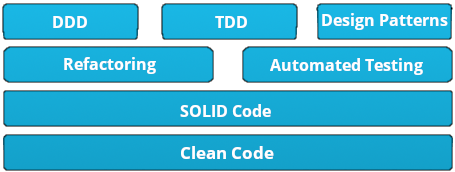
The focus of the DevNet certification are the Design Patterns. These are general, reusable solutions to commonly occurring problems, they are formalized best practices that the programmer can use when writing code. These patterns could be categorized in:
- Creational (object creation).
- Structural (object relationship).
- Behavioral (object interaction and responsibility).
- other patterns like Concurrency (multi-threaded systems).
Looking in which category the MVC pattern may fall into, I’ve come to realize that it’s an Architectural pattern and not a design pattern. Architectural patterns are similar to design patterns but with a broader scope.
I found a nice blog post from Vijini Mallawaarachchi, with a brief explanation of the 10 most common architectural patterns, below you may find her pros and cons of architectural patterns.
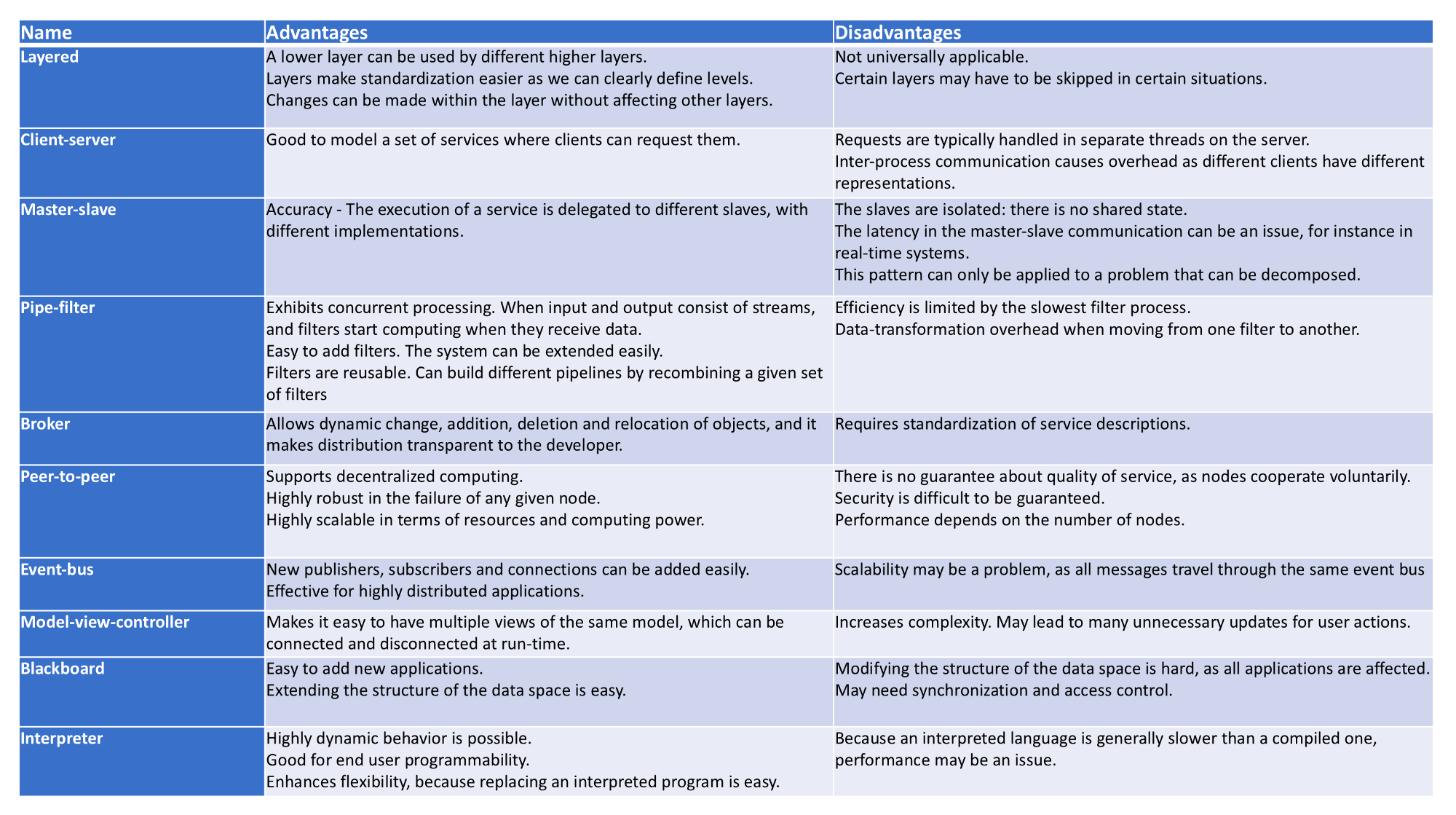
As stated in the exam overview, We are focusing specifically in two patterns MVC(architectural) and Observer(design - behavioral).
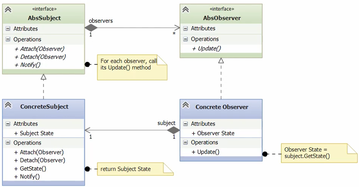
Observer Design Pattern
Also known as Dependents or Publish-subscribe pattern, as a behavioral pattern, is used to control the operations and interactions of objects, it defines a one to many relationship between a set of objects, when the state of one of them changes all the dependents are notified.

A really useful thing to consider is looking for Unified Modeling Language (UML) Diagrams, a standardized modeling language consisting of an integrated set of diagrams, developed to help system and software developers for specifying, visualizing, constructing, and documenting the artifacts of software systems, as well as for business modeling and other non-software systems.
This is a broad topic that we are not diving into here, but to provide additional information, the figure below shows an Observer Pattern UML Diagram, where you can see the interactions between the different objects and the required methods, this UML follows the SOLID principles from coding best practices.
MVC Design Pattern
This pattern is often called Model Template View (MTV), and is commonly used in web applications, as it separates functionalities between components in an application, providing good scalability.
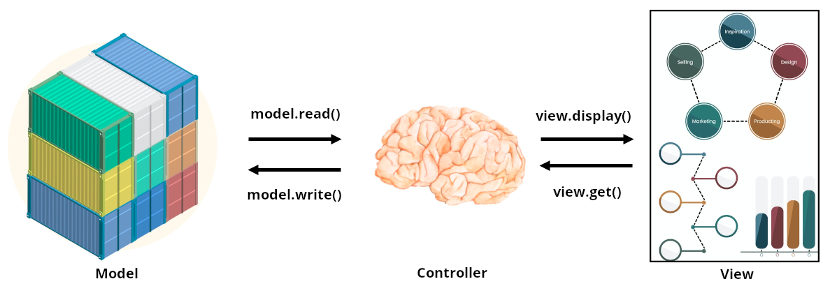
Breaking down the components we can see that the model provides an interfaces to the data used by the app, the view serves as a frontend for user interaction without any data processing and the controller would apply the app logic, it’s the intermediate component that reads and writes to the model and also interacts with the view to display the information.
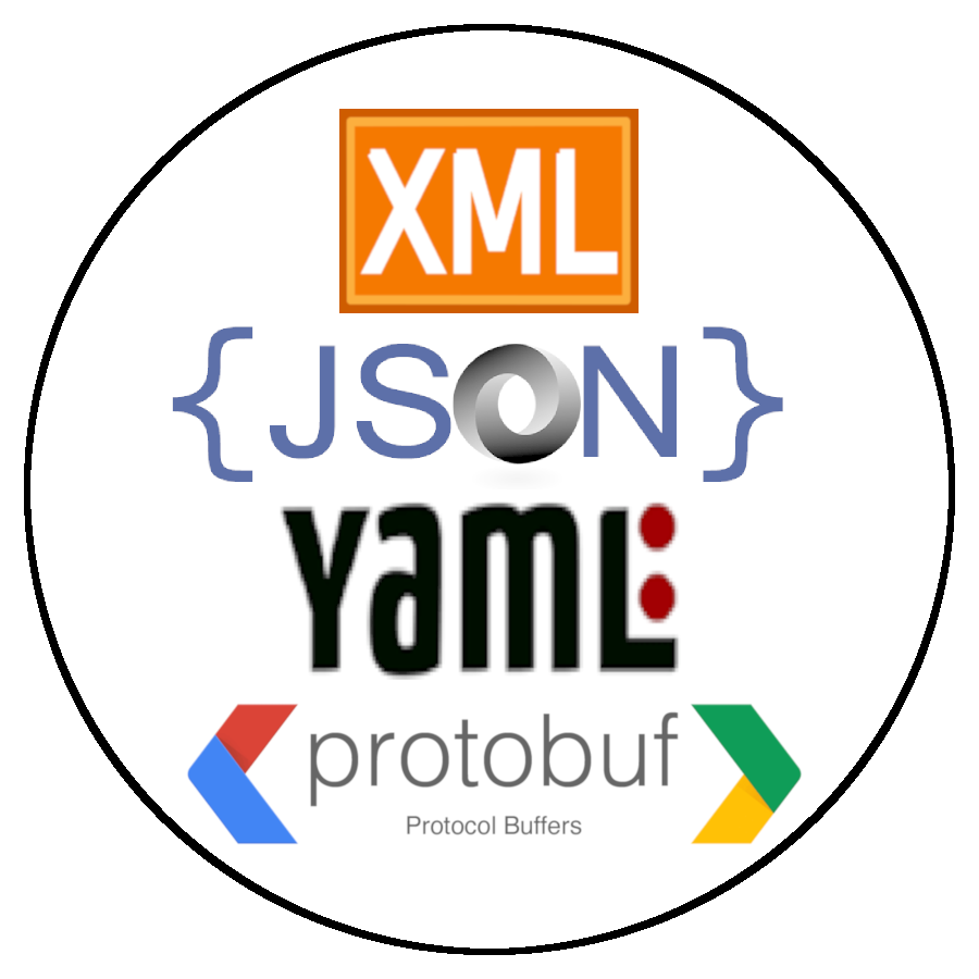
Data Formats
XML (eXtensible Markup Language), JSON(JavaScript Object Notation) and YAML(YAML Ain’t Markup Language), are the most commonly used data formats or data serialization tools to decouple data from code whenever we are communicating with our infrastructure, additionally is easier to load into memory without parsing.
XML
XML is a markup language much like HTML, it was designed to store, transport data and to be self-descriptive. XML is software- and hardware-independent since stores data in plain text format.
XML and HTML were designed with different goals, XML was designed to carry data and HTML was designed to display data. XML tags are not predefined like HTML tags are.
An XML Schema describes the structure of an XML document, like grammar rules, semantic constraints, and other data modeling aspects.
There are several XML Schema languages, like DTD, XSD and RelaxNG, these schemas would be relevant for validation purposes, like when translating YANG data models to XML schemas, which then can be used for validating specific XML documents such as client requests, server responses or notifications, perhaps also taking into account additional context such as active capabilities or features.
From our client side perspective, we can infer the attributes and properties from the YANG model directly.
The structure of an XML file with an hypothetical class zzz:Object resembles this structure:
<?xml version="1.0" encoding="UTF-8" ?>
<zzzObject>
	<attributes>
		<property1>value1</property1>
		<property2>value2</property2>
		<property3>value3</property3>
	</attributes>
	<children>
		<zzzChild1>
			<attributes>
				<childProperty1>childValue1</childProperty1>
				<childProperty2>childValue1</childProperty2>
			</attributes>
			<children />
		</zzzChild1>
	</children>
</zzzObject>
Is worth mentioning that there is a query language named XPath, which is used to navigate through elements and attributes in an XML document. Like working with traditional file systems, XPath uses path expressions to select nodes or node-sets in an XML document, this is really helpful to manipulate NETCONF responses for example, since it uses XML as its encoding format.
Taking our example above for zzzObject, the XPath expresion /root/zzzObject[.//atributes/property1] would select the zzzObjects (if we had more than one) that had the property1 attribute. You can find a good tutorial for XPath in w3schools’s webpage.
JSON
JSON is easy for humans to read and write and easy for machines to parse and generate. It is based on a subset of JavaScript and is built on two structures:
- A collection of name/value pairs. In Python, this is realized as a dictionary.
- An ordered list of values. In Python, this is realized as a list.
A JSON structure of hypothetical class zzz:Object resembles this structure:
{
  "zzzObject" : {
    "attributes" : {
      "property1" : "value1",
      "property2" : "value2",
      "property3" : "value3"
    },
    "children" :{
      "zzzChild1" : {
        "attributes" : {
          "childProperty1" : "childValue1",
          "childProperty2" : "childValue2"
        },
        "children" : []
      }
    }
  }
}
YAML
YAML is easier for humans to read and write than XML or JSON. Nearly every YAML file starts with a list. Each item in the list is a list of key/value pairs, commonly called a “hash” or a “dictionary”.
Additionally YAML files can optionally begin with --- and end with ..., this is recommended to not accidentally truncate data.
All lines beginning at the same indentation level and starting with a - (a dash and a space), are members of a list.
Dictionaries are represented in a simple key: value form (the colon must be followed by a space)
More complicated data structures are possible, such as lists of dictionaries, dictionaries whose values are lists or a mix of both.
A YAML structure of hypothetical class zzz:Object resembles this structure:
---
zzzObject:
  attributes:
    property1: value1
    property2: value2
    property3: value3
  children:
    zzzChild1:
      attributes:
        childProperty1: childValue1
        childProperty2: childValue2
...
Protobuf
Protocol buffers are Google’s language-neutral, platform-neutral, extensible mechanism for serializing structured data, like XML, but smaller and faster. You define how you want your data to be structured once (which forces you to have defined schema), then you can use special generated source code to easily write and read your structured data.
Some downsides for this language could be the dependency in google compiler (protoc), or the need to recompile, due to bug fixes, etc., and this could break your code at one point. Additionally, like with any structured language, the overhead of maintaining the schema could be cumbersome.
Protobuf has different versions but whenever I refer to protobuf in my posts, I’ll be referring to proto3 version.
The protobuf schema is defined in a “.proto” file which has several components, but just to point out the most relevants:
- syntax defines the protobuf version that you are using.
- message defines the structured objects and its specified fields (name/value pairs), one for each piece of data that you want to include in this type of message, each field has a name and a type.
These names and types also have a field number, these field numbers are used to identify your fields in the message binary format, and should not be changed once your message type is in use. Field numbers should be sorted by message element occurrence frequency. It is recommended to also leave some room for some of these elements that might be added in the future, this recommendation is related to protobuf encoding. - Message fields can be singular (one or none of this field, but no more than one) or repeated which can be repeated any number of times (like arrays). The order of the repeated values will be preserved.
- services are use to define RPC service interfaces using the message types previously defined
We can see a real case example in this snippet of gnmi.proto file, I just took different sections of this file to show a broad idea of this schema structure:
syntax = "proto3";

service gNMI {
  rpc Capabilities(CapabilityRequest) returns (CapabilityResponse);
  rpc Get(GetRequest) returns (GetResponse);
  rpc Set(SetRequest) returns (SetResponse);
  rpc Subscribe(stream SubscribeRequest) returns (stream SubscribeResponse);
}

// SubscribeRequest is the message sent by the client to the target when
// initiating a subscription to a set of paths within the data tree.

message SubscribeRequest {
  oneof request {
    SubscriptionList subscribe = 1; // Specify the paths within a subscription.
    Poll poll = 3;                  // Trigger a polled update.
    AliasList aliases = 4;          // Aliases to be created.
  }
  repeated gnmi_ext.Extension extension = 5;
}

// SubscribeResponse is the message used by the target within a Subscribe RPC.

message SubscribeResponse {
  oneof response {
    Notification update = 1;          // Changed or sampled value for a path.
    bool sync_response = 3;
    Error error = 4 [deprecated=true];
  }
  repeated gnmi_ext.Extension extension = 5;
}

// SetRequest is sent from a client to the target to update values in the data
// tree.
message SetRequest {
  Path prefix = 1;                // Prefix used for paths in the message.
  repeated Path delete = 2;       // Paths to be deleted from the data tree.
  repeated Update replace = 3;    // Updates specifying elements to be replaced.
  repeated Update update = 4;     // Updates specifying elements to updated.
  repeated gnmi_ext.Extension extension = 5;
}

// SetResponse is the response to a SetRequest, sent from the target to the
// client.message SetResponse {
  Path prefix = 1;                      // Prefix used for paths.
  repeated UpdateResult response = 2;
  Error message = 3 [deprecated=true]; // The overall status of the transaction.
  int64 timestamp = 4;                 // Timestamp of transaction (ns since epoch).
  repeated gnmi_ext.Extension extension = 5;
}
So, now that we have the schema, we could transform this into integration classes for any supported language, like Python, by using the “protoc” compiler, which would generate the code you need to work with the message types defined in the .proto file.
With the generated code, we can for example, import it to our python code, where we can make calls to these functions.
Protobuf is used in network management protocols like gNMI and gNOI, but it is more complex than the previous data formats, so don’t worry if it is not completely clear right now.
Data Models
Data models define data objects and relationships among data objects for a domain of interest, it allows the developers understand the structure for how data is stored.
YANG is a data modeling language defined in RFC 6020, focused on network constructs, modeling configuration and state data manipulated by the Network Configuration Protocol (NETCONF), but is worth noting that RESTCONF also supports YANG models.
Devices may support different YANG models to represent the same data in different ways.
More information regarding device configuration management will be available on the Infrastructure and Automation post in this same DevNet Collection
Cisco software supports two type of YANG data models, Native and Open.
Native data models are specific to Cisco and are not interoperable with other platforms. They closely mirror the structure of the CLI.
Open data models provide a common interface across multiple platforms. Cisco supports a number of open data models from both the IETF and OpenConfig standards bodies.
Cisco YANG models can be found in a GitHub repository, from here we can navigate to a specific platform and version.
A YANG module is best understood when visualized as a tree structure, one way to do this is to use pyang, a tool that produces a tree view showing the structure of a module as well as field names and types.
pyang -f tree openconfig-interfaces.yang
        module: openconfig-interfaces
          +--rw interfaces
             +--rw interface* [name]
                +--rw name -> ../config/name
                +--rw config
                 | +--rw name? string
                 | +--rw type identityref
                 | +--rw mtu? uint16
                 | +--rw loopback-mode? boolean
                 | +--rw description? string
                 | +--rw enabled? boolean
                 +--ro state
                 | +--ro name? string
                 | +--ro type identityref
                 | +--ro mtu? uint16
                 ...
YANG Relationship to XML and JSON
A common source of confusion is the relationship between YANG data models and encoding formats such as XML/JSON.
YANG represents the data on a device in an abstract way, but does not contain actual device configuration or operational data; it simply shows the structure. In other words, YANG forms the template from which XML/JSON data is generated and does not represent the actual data.
If you would like to go deeper into the components of a YANG model, keep reading, if this is not the case, you can move forward to the version control section
YANG Breakdown
Next we define some important components used in YANG that will help understanding the language specifics.
- Modules are a self-contained tree of nodes, they are the smallest unit that can be "compiled" by YANG tools. Modules contain:
- Boilerplates
- Types (built-in or derived types)
- Modular groupings
- Top-level container that defines tree of data nodes
- Types take a string argument that would be its name, followed by an optional block of substatements that are used to put further restrictions on the type. These types can be:
- Built-in, like binary, bits, boolean, decimal64, int32, etc.
- identity, used to identify something with explicit semantics and can be hierarchical, they are globally unique, abstract, and untyped.
- typedef, define derived types from base types, a base type can be either a built-in type or a derived type itself, allowing a hierarchy of derived types.
- YANG defines four types of nodes for data modeling:
- Leaf Nodes, contain simple data like an integer or a string, it has exactly one value of a particular type and no child nodes.
- Leaf-List Nodes, are a sequence of leaf nodes with exactly one value of a particular type per leaf.
- Container Nodes, are used to group related nodes in a subtree. A container has only child nodes and no value, they may contain any number of child nodes of any type (including leafs, lists, containers, and leaf-lists).
- List Nodes, define a sequence of list entries, each entry is like a structure or a record instance, and is uniquely identified by the values of its key leafs. A list can define multiple key leafs and may contain any number of child nodes of any type.
The list's key statement MUST be present if the list represents configuration, and MAY be present otherwise, takes a string as an argument with a space-separated list of leaf identifiers (key leafs) of this list, e.g. this is represented in the previous pyang tree within brackets "[name]".
- Grouping is a reusable set of nodes (containers and leaves) that can be included (instantiated) in a container with the "uses" statement. A grouping on its own does not add any nodes to the module in which it is defined or imported.
- The import statement references external modules, a submodule MUST NOT import its own module and there MUST NOT be any circular chains of imports.
When a definition in an external module is referenced, a locally defined prefix MUST be used, followed by ":", and then the external identifier. - augment allows a module to insert additional nodes into data models. It defines the location in the data model hierarchy where new nodes are inserted, and the "when" statement defines the conditions when the new nodes are valid. (conditional)
- deviation defines a hierarchy of a module that the device does not implement faithfully. The argument is a string that identifies the node in the schema tree where a deviation from the module occurs, this node is called the deviation's target node. The contents of the "deviation" statement give details about the deviation.
A good example to visualize some of these constructs together would be, for example, the openconfig-interfaces YANG model.
I would highly recommend you to go through different models and try to understand the language, eventually with practice it will become familiar, like with any new concept.
module openconfig-interfaces {

////// [WS] Boilerplate /////
  yang-version "1";

  // namespace
  namespace "http://openconfig.net/yang/interfaces";

  prefix "oc-if";

  // import some basic types
  import ietf-interfaces { prefix ietf-if; }
  ...

  // meta
  organization "OpenConfig working group";

  contact
    "OpenConfig working group
    netopenconfig@googlegroups.com";

  description
    "Model for managing network interfaces and subinterfaces..";

  oc-ext:openconfig-version "2.3.0";

  revision "2018-01-05" {
    description
      "Add logical loopback to interface.";
    reference "2.3.0";
  }
  ...

///// typedef statements [WS] No identities types used here, only derived /////

  typedef base-interface-ref {
    type leafref {
      path "/oc-if:interfaces/oc-if:interface/oc-if:name";
    }
    description
      "Reusable type for by-name reference to a base interface...";
  }

  typedef interface-id {
    type string;
    description
      "User-defined identifier for an interface...";
  }

///// grouping statements /////

  grouping interface-ref-common {
    description
      "Reference leafrefs to interface / subinterface";

    leaf interface {
      type leafref {
        path "/oc-if:interfaces/oc-if:interface/oc-if:name";
      }
      description
        "Reference to a base interface...";
    }

    leaf subinterface {
      type leafref {
        path "/oc-if:interfaces/" +
          "oc-if:interface[oc-if:name=current()/../interface]/" +
          "oc-if:subinterfaces/oc-if:subinterface/oc-if:index";
      }
      description
        "Reference to a subinterface...";
    }
  }

  grouping interface-ref-state-container {
    description
      "Reusable opstate w/container for a reference to an
      interface or subinterface";

    container state {
      config false; // [WS] Read only
      description
        "Operational state for interface-ref";

      uses interface-ref-common;
    }
  }

  grouping interface-ref {
    description
      "Reusable definition for a reference to an interface or
      subinterface";

    container interface-ref {
      description
        "Reference to an interface or subinterface";

      container config {
        description
          "Configured reference to interface / subinterface";

        uses interface-ref-common;
      }

      uses interface-ref-state-container;
    }
  }
  ...
  grouping subinterfaces-top {
    description
      "Subinterface data for logical interfaces associated with a
      given interface";

    container subinterfaces {
      description
        "Enclosing container for the list of subinterfaces associated
        with a physical interface";

      list subinterface {
        key "index";

        description
          "The list of subinterfaces (logical interfaces) associated
          with a physical interface";

        leaf index {
          type leafref {
            path "../config/index";
          }
          description
            "The index number of the subinterface -- used to address
            the logical interface";
        }

        container config {
          description
            "Configurable items at the subinterface level";

          uses subinterfaces-config;
        }

        container state {

          config false;
          description
            "Operational state data for logical interfaces";

          uses subinterfaces-config;
          uses subinterfaces-state;
        }
      }
    }
  }
  ...
}
![]()
Version Control
Version Control Systems, help us track changes in source code (or any file) during the software development process. There are two main categories of version control systems, one is centralized and the other one distributed.
In a centralized or also called client - server version control systems as the name implies, a number of users or clients connect to the repository (server), which provides access to these clients, pretty similar to FTP. The main characteristic is that everything must be sent and received from this central repository.
On the other hand are the distributed systems, where each user has their own copy of the entire repository, not just the files but the history as well, letting every user to make changes to that local repository before pushing them to the “main” repository, this means that the user doesn’t need connectivity to the main server.
These repositories could be considered as the source of truth, were different components of the software development process could integrate to. For example, some of the different components that could leverage this information are:
- Project Management Tools. (Jira)
- Bug Trackers. (Bugzilla)
- Build Machines or CI/CD for automated tests and deployments (Jenkins)
Git
Git is a distributed version-control system and it is designed for coordinating work among programmers, but it can be used to track changes in any set of files. Its goals include speed, data integrity and support for distributed, non-linear workflows.
Disadvantages
- Not ideal for binary files (e.g. Video or Big Data)
Advantages
- Fast
- Smart
- Flexible
- Safe
An important disclaimer is to remember that version control is not a backup, you still need a backup strategy.
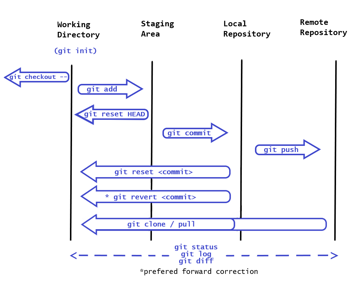
There are three main sections in a local Git project, the workspace directory, the staging area (Index) and the local repository.
- Local workspace: Is where you store, use or modify on disk, source code files, binaries and whatever you have controlled within a git repository.
- Staging area: Is a file, generally contained in your Git directory, which stores information about what will go into your next commit, an intermediary storage area for items to be synchronized in the repository.
- Local repository: or Git directory is where Git stores the metadata and object database for your project (all committed items).
Branching and Merging are extensive topics on their own, but is important to know the basics.
Git branches are effectively a pointer to a snapshot of your changes, which lets you brach out another stream from the master branch. This is pretty common in the Git workflow. You could move between braches with the git checkout [branch] command.
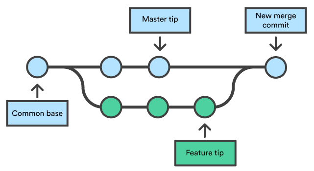
After branching, each branch would develop in an isolated matter until there is the need to fork some of the history back together and there is where merging comes in. Merging lets you take the independent lines of development and integrate them into a single branch.
The merge is unilateral, which means that the current branch will be updated to reflect the merge, but the target branch will be completely unaffected. (e.g. If you merge the master branch with the feature, now the master branch includes that feature, but the feature branch do not include the master)
Is common knowledge that branching is easy but merging is hard, this is because when merging, is common to stumble upon conflicts, triggered when there is a change affecting the same code, whenever this happens Git will ask the developer to resolve them.
For more information regarding the use of braches, you could refer to Atlassian’s tutorials. There is also the entire Pro Git book, written by Scott Chacon and Ben Straub, within git-scm.com webpage, which I would highly recommend.
Next I try to summarize key basic commands from Git that I consider relevant at the time of this writing:
- git init - Create an empty repository, is not necessary when cloning an existing repo.
- git status - List the status of the repository, like which files are untracked.
- git log - Display the commit history of the repo.
- git diff - Show changes between commits, commit and working tree, etc.
- git checkout - Switch branches or restore working tree files or commits. Including -- discards changes in the working directory.
- git add - Stage the changes for the next commit, it could include directories or specific files.
- git reset HEAD - Unstage the changes to the working directory. Using [commit] instead of HEAD allows you to reset current HEAD to the specified state or commit.
- git commit -m "Message" - Commit an staged snapshot, you could include a message as shown to describe the change.
- git revert [commit] - Creates a new commit that undo all changes made in the specified commit, then apply it to the current branch.
- git push - Push all necessary commits and objects to the remote repository.
- git clone - Clone a repository onto the local machine.
- git pull - Fetch an specified remote's copy and merge it into the local copy
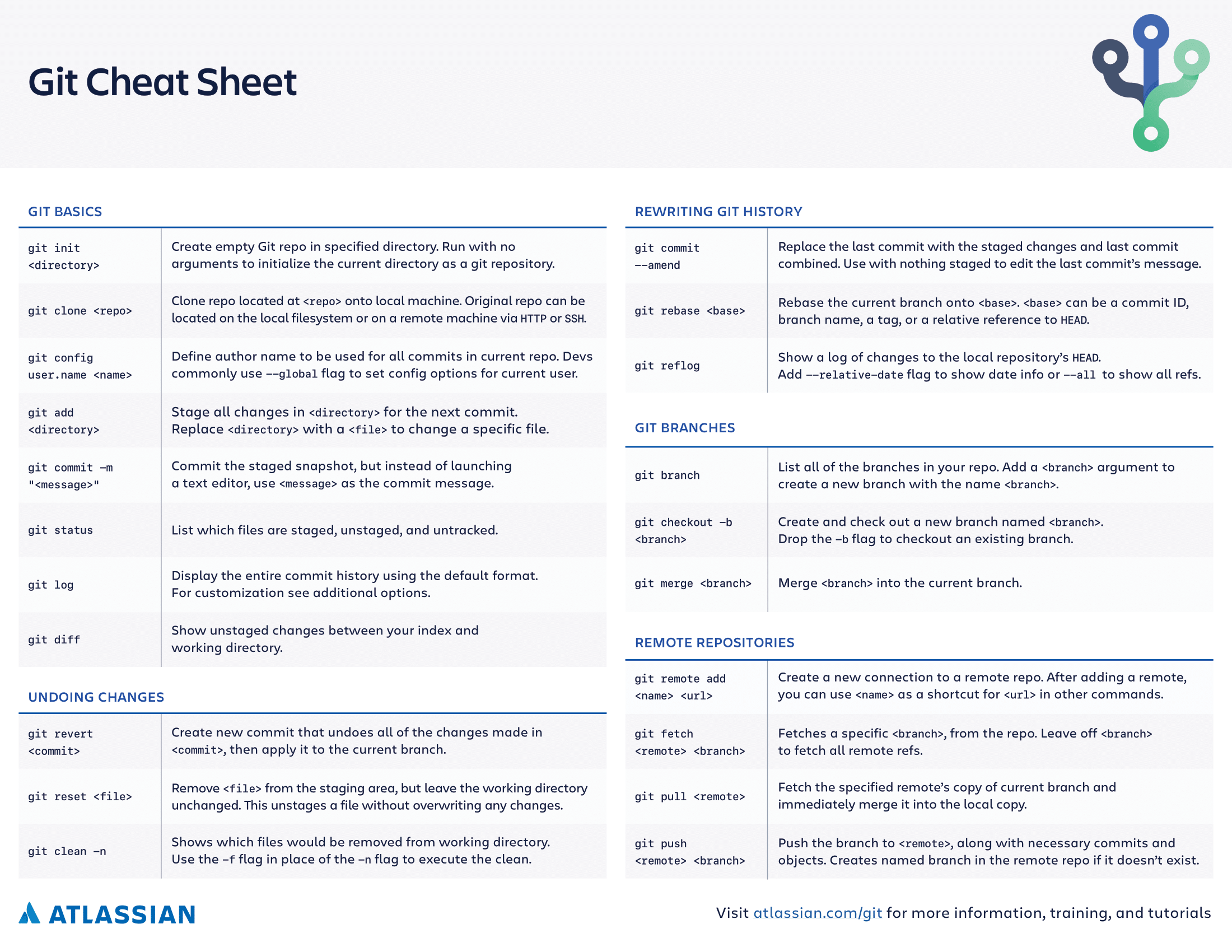
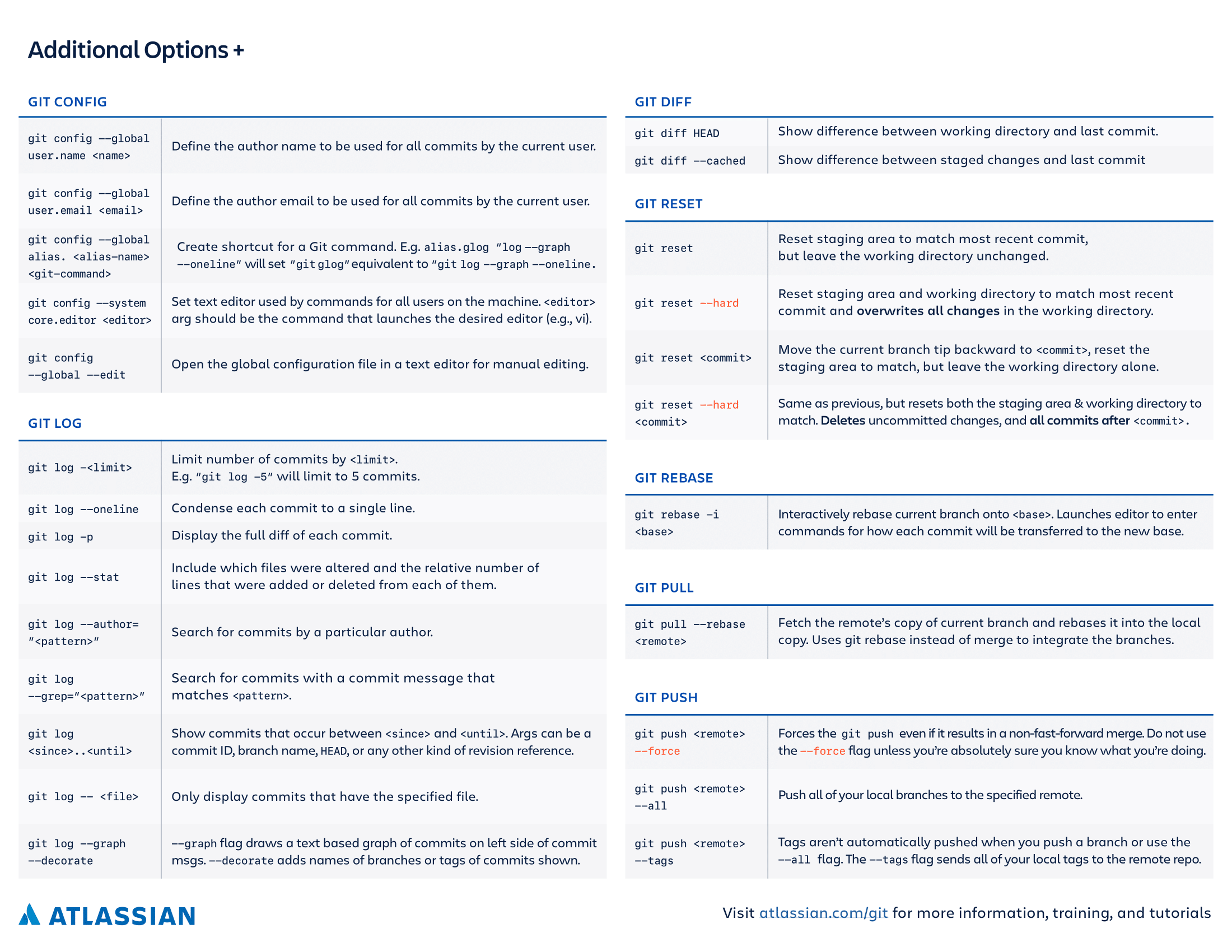
In order to save some time when you just can’t remember all the commands, I just leave Atlassian’s Git Cheat Sheet below, which I find really useful.
The Open Source Workflow
When working on an open source project, there is a usual way of working that allows anyone to contribute to the project, without the owner resigning control of the project. This workflow is not only used for open source projects, as many companies use it for internal development.
The usual (GitHub) contribution workflow for a change in a project would be as follows. Here we assume that we have access to the source repository:
- Clone the repository to work on them locally
- Branch out
- Add commits
- Push changes to the repo
- Open a pull request to initiate discussion about your commits
- Discuss and review your code
- Deploy from a branch for final testing in production before merging to master.
- Merge now that your changes have been verified in production.
Now, open source projects involve a great number of contributors and these usually don’t have access to the source repository, being external resources to the project. How can they help? By forking the project.
Forking, is an operation which is used by a certain git workflows, made popular by GitHub, called the Fork and Pull Workflow.
Creating a fork is producing a personal copy of someone else’s project. Forks act as a sort of bridge between the original repository and your personal copy, bridge that a cloned repository doesn’t have.
So now, as an external contributor, the workflow now would be:
- Fork the source repository
- Clone the repository to work on them locally
- Add commits
- Push changes to the forked repo
- Send a pull request to the source project maintainer
- The maintainers would discuss and review the code
- If they agree on including the changes made, they would pull these changes from the forked repository to the source repo.